Model-View-Controller Device Software Design Pattern
Challenge
IoT devices have a common set of concerns:
- reporting the current state of the device, attached sensors, and actuators
- processing control messages (both remote and local)
- presenting status information
The device software should also be easy to test and reuse across multiple projects, hardware platforms, languages, and SDKs. Some devices are ‘one-way’ only reporting state or taking action, while others are ’two-way’, performing both of these actions. The software design pattern should be generally composable to support all these uses as well as accommodate a flexible variety of peripherals, command sources, and interfaces.
Solution
An IoT device software design pattern based on the Model-View-Controller design pattern.
Basic Model View Controller
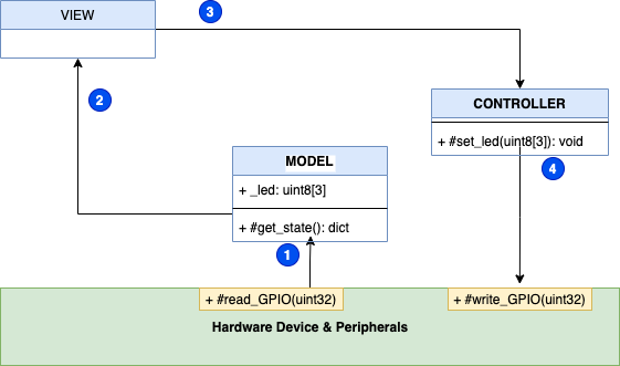
The model component’s concern is to represent the overall state of the device: signals, metrics, peripherals, display data, and current state of the control variable(s). The view component handles the presentation of the data from the model. The controller is responsible for taking actions to change the state or configuration of the device and peripherals.
-
The model, and only the model reads from the device.
-
The view only reads from the model and never the hardware directly.
-
If the view needs to effect some local presentation (such as turning on an attached LED), the view should use the controller to make that change.
-
Only the controller is allowed to write to the hardware.
Basic Model View Controller Considerations
The concerns of reading and writing to the hardware are separated between the model (read-only) and the controller (write-only). This separation facilitates testing and mocking (See Mocks aren’t Stubs for a brief intro to mock objects and how they can be used for testing software) and can also be used to limit access to mutating changes (writes) that may require privileged access or other security (including audit).
The model component’s concern is to scan the inputs on a regular basis (such as a timer interrupt) or when changes occur (such as an edge trigger). For certain hardware platforms it may be necessary for the model to set up triggers or callbacks. While this set up often involves the writing of registers, that set up does not violate the model’s restriction to only read from the hardware.
Note that there are no (exposed) setters as part of the model. That is because all activation of changes should be handled by the controller and the model would record these changes when measured directly from the hardware.
The model is best implemented by a Singleton design pattern and is readily extensible with blocking and non-blocking calls.
Practical Model View Controller
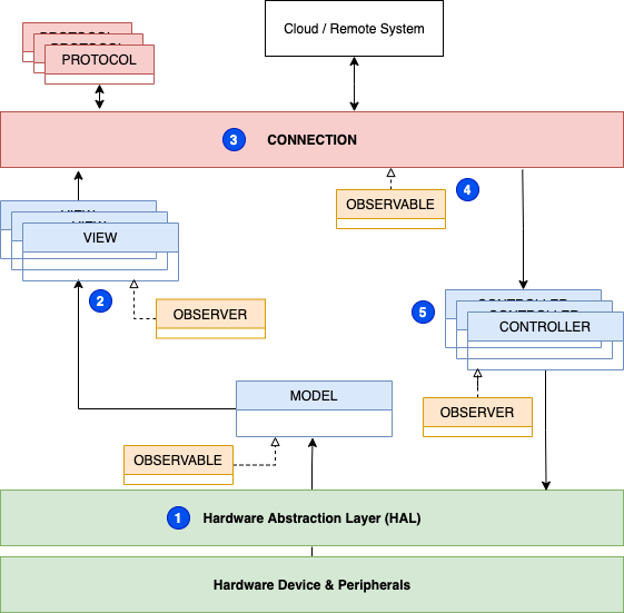
Many hardware platforms would seemingly require a violation of the model-controller read-write separation. For example, registers with bit masks for multiple GPIO lines or other registers with different read/write behavior. Multiple views may also be required, such as one for local LEDs or displays and another to handle formatting data into JSON or Protobuf for remote systems. Grouping actuations (like Display, LEDs, etc) also leads to using multiple controllers.
-
A Hardware Abstraction Layer (HAL), a Facade pattern, where the details of bit masks or GPIO numbers or other specifics can be abstracted and made semantic to the application at hand by creating API calls such as
#LED_Onwhich would wrap the functionality of setting a particular GPIO Pin high or low. -
Multiple views now read the model data.
-
The connection instantiates protocol as needed to communicate locally and remotely.
-
Communications received from the remote systems are held in an Observable implementation by the connection.
-
Multiple controllers subscribe to the connection Observable as Observers.
Practical Model View Controller Considerations
The HAL uniquely contains the mapping of hardware specifics to the application representation. This facilitates testing as a mock HAL can be used when the hardware is not available. This Facade aids portability in that the implementation of #LED_On can be modified to active-high or active-low logic, GPIO Pin numbers changed, etc.
Having multiple views read the Singleton model could cause exhaustion of resources or other run-time problems. Use of the Observer Pattern as intermediary can break this deadlock as well as provide a convenient integration point to install additional views for debug/logging or other uses without impacting the model. The model implements the Observable interface while the various views implement Observer. The views then register with the model at run-time avoiding the creation on any dependencies.
The connection implements the Strategy Pattern as well as the Observable interface. As a Strategy the connection instantiates protocol objects as needed to varying transports (like MQTT and topic name). The protocol will also write to a connection managed Observable. The details of topic, transport, remote system, etc. are all separated from the reporting (view) and processing (controller) facilitating testing through mocks and composability for different applications (such as some devices only having some groups of signals, etc.).
Considerations
Safety
In many systems, particularly those that actuate physical systems like motors, solenoids, or relays, pathways for locking out or failing safe for those systems should be kept as short as possible. When at all possible, these lockout systems and sensors should be configured so that they disable actuation of potentially dangerous systems. For example, place a limit switch in series with a motor activation circuit. This ensures that no software failure, attack, or disintermediation can defeat the designed safety controls.
Because of this critical relationship of the safety controls to device operation, the status of the sensors and controls should be monitored and reported. Here too, care must be taken to ensure that the monitoring of the signal cannot in any way affect the function of the control. One common way to do this would be to use a buffer, follower, or open drain device to isolate the control signal from the measurement system. Consider if the signals were to be routed to GPIO pins, such a buffer would prevent a misconfiguration of the pinmux to output from defeating the safety control.
For any device and system, first review the components and subsystems as to how they affect the overall safety of the system and minimize the potential impact of software errors or attacks to the system. A similar discussion of security and attack surfaces should also be undertaken, but that is beyond the scope of this document.
Local Buttons
When the user pushes the local button (on a GPIO input for example), how shall this be processed? We desire to have low-latency response and the sytem should function without cloud connection. But when we do have connectivity, the mobile app should show the status also with low latency.
-
The button state (up/down/edge/etc) should be monitored and maintained by the model.
-
Subscribed views can monitor these signals:
-
The first view would request a ’local’ protocol from the connection and report state.
-
The second view would report to any remote systems.
-
-
The ’local’ protocol implementation would update the connection managed Observable
-
A controller is subscribed to this Observable as an Observer and would take appropriate action.
The full separation of concerns is maintained, while full local-only functionality is maintained and any remote systems kept up to date.